Data Manager & Shift Leader for Run 3 – Notes
Useful links
Acronyms
Definition |
Note |
|
|---|---|---|
AI |
Analog Inputs |
|
BE_OP |
machine operations |
|
BPIM |
Beam Phase and Intensity Monitor |
|
BCM |
Beam Conditions Monitor |
or Main Background Monitor |
CCC |
CERN Control ROOM |
|
CR |
Control Room |
|
CSAM |
CERN Safety Alarm Monitoring |
|
DAI |
Data Acquisition Infrastructure |
|
DDS |
Detector Safety System |
|
DI |
Digital Inputs |
|
DM |
Data Manager |
|
DQ |
Data Quality |
|
ECS |
Experiment Control System |
|
EIC |
Engineers-In-Charge |
accelerator operations |
EN-CV |
CERN cooling group |
|
E N-EL |
CERN electrical service |
|
ESO |
Electrical Safety Officer |
|
FRS |
Fire and Rescue Service |
|
FSM |
Finite State Machine |
|
HV |
High Voltage |
|
IHM |
Human-Machine Interface |
|
LACS |
LHC Access Control System |
|
LASS |
LHC Access Safety System |
|
LBDS |
LHC Beam DUmp System |
|
L EXGL IMOS |
Large Experiment Group Leader In Matters Of Safety |
|
LPC |
LHC PRogram Coordinator |
|
MAD |
Material Access Device |
|
MC |
Machine Coordinators |
Run Chief at CCC |
MD |
Machine Development period |
|
PAD |
Personnel Access Device |
|
PT |
Temperature Probes |
|
SL |
Shift Leader |
|
SL IMOS |
Shift Leader In Matters Of Safety |
|
RC |
Run Coordinator |
|
RPE |
Radiation Protection Expert |
|
RSO |
Radiation Safety Officer |
|
TSO |
Territorial Safety Officer |
Phone Numbers
Prefix for CERN fixed numbers: +41 22 76 xxxxx prefix for CERN mobile numbers: +41 75 411 xx xx
Name |
Number |
|---|---|
CERN HSE-RP piquet |
(7 52 52) |
CCC |
+41 22 76 (7 76 00) |
CCC Techical Infrastructure |
(7 22 21) |
Data manager |
+41 22 76 (6 35 96) |
DSS piquet/GLIMOS |
(16 80 00) |
EP-DT magnet and DSS piquet |
(16 20 82) |
Fire and Rescue |
+41 22 76 (7 44 44 urgent) (7 48 48 non-urgent) |
LEXGLIMOS |
(16 90 56) |
LHCb RPE piquet |
(16 80 00) |
Run Chief |
+41 22 75 411 1868 (+41 22 76 161868) |
Run Coordinator |
+41 22 76 (6 32 18) |
Shift Leader |
+41 22 76 (fixed=63595, mobile=161866) |
Important
☐ subscribe to
lhcb-shift-leadersandlhcb-data-managersmailing list☐
LHCB_Sand Control Room access permission
Shifter Duties
☐ SL follow the Run Meeting when scheduled
☐ SL take data with the Run Control, Operate Voltages and sub-detectors in the
Big Brother, handle handshakes and interlocks☐ DM check data quality and do data management
☐ answer CCC phone when LHC call (if needed take notes for RC)
☐ Mostly relay information about the plan of the day, ongoing activities, accesses, problems, LHC status, sub-detectors information
☐ DM replace SL when outside CR
☐ write anything happen in the logbook
☐ Control Room Doors should be closed by 7pm
☐ Global monitoring panel of LHC: check system status (if problem report/call CCC?)
☐ Check if LHCb Timing is synchronous with LHC
Data Manager Duties
☐ check the plots in the “Shift” folder continuously. ## SLIMOS Duties
☐ Follow up DSS alarms, acknowledge and reset.
Daily ToDo
☐ if night shifter print
Who's on shift today@ 6am (select printer “color”, printer near keys’ cabinet)☐ SL at the end should write a
Shift Summaryentry in the logbook: what happened in the LHC/LHCb and outstanding items to be done using proposed structure☐ SLIMOS check to be logged into DSS as
slimosand two LEDs next toAliveare alternating (if not restart app or reboot the PC)
Module 1a: Central Shifters
Shift Leader (SL) and Data Manager (DM) refer directly to the Run Chief (while on shift and to the Run Coordinator in general) and in alternative to the Run Coordinator. For safety matter, they refer directly to the (LEX-)GLIMOS.
Tasks during operations are provided to you by the Run Chief and/or the Run Coordinator. SLs are in charge of safety but they are not in charge of security!
LHCB_S and Control Room access are mandatory for both DM and SL,
while LHCB_U is strongly recomended for SL.
Warning
Never ignore DSS or Level 3 alarms: call piquet and follow procedure explained in safety course
Danger
Meeting point for emergencies = building 2890, always carry CERN Access Card
Login for control room screens: - user: lhcb_shift - pswd: top of whiteboard, with ! in front…
Who you gonna call?
If you know you cannot make it on time, call the current Shift Leader and call the Run Chief
If the incoming shifter does not show up within 15 minutes after the start time of the shift, the outgoing shifter should call the Run Chief
The experts are also available to answer the phones, but first you should always call the sub-detector piquet of the concerned system
If the call concerns the LHC or something that needs more escalating, call the Run Chief as well
If there is a safety issue or an alarm, call 168000 (DSS piquet or GLIMOS)
If in doubt about the LHC doings, call the CCC to clarify
LHCb Run Control
The
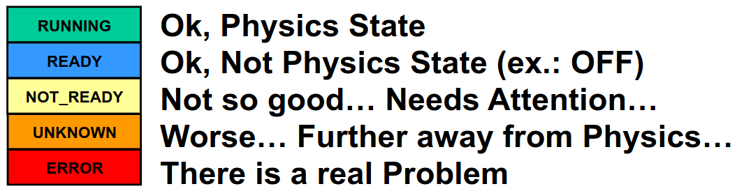
LHCb Run Controlis the main panel to control all devices needed for data taking: keep itRUNNINGconfiguration given by the RCThe
Big Brother: Main panel to control HV, interfaces to the LHC, clock, BCM, magnet. never ignore anERROR.The
Alarm Screen: Never ignore alarms, always follow-up. Any observation, write it in the logbook. If you are in doubt, better call the concerned sub-system piquet.
LHC cycle
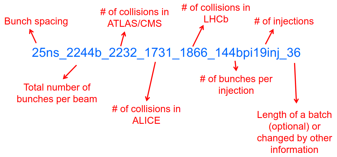
Handshake: \(Injection-> Adjust-> Dump\). Done between LHC and all 4 experiments, controlled via Big BrotherLHC filling scheme, naming convention
LHCb States |
Note |
|---|---|
INJECTION |
@ 450 GeV |
RAMP |
@ 6.8 TeV |
SQUEEZE |
beam transversally smaller |
PHYS_ADJUST |
|
PHYSICS |
|
ADJUST |
|
DUMP |
get rid of beams |
EOF |
|
NO_BEAM |
LHCb Timing
The LHCb timing (clock) is centrally controlled/monitored via a set of electronics boards called RFRx, RF2TTC and BPIM. Check status on Big Brother. Two modes of operations:
INTERNAL: clock is generated locally in LHCb for the whole detector
EXTERNAL: clock is received via the LHC and it is in phase with the beams (synchronous)
LHCb safety
LHCb Main Background Monitor rearms automatically if dump was not by itself \(->\) FSM state changes ABORT_PMT \(->\) PM_READY \(->\) READY
if BCM dumps, and FSM stays in PM_READY waiting for manual Rearm \(->\) CALL CCC “we have probably dumped and we are investigating”, and CALL RC before rearming -use the
Send to logbookbutton to record unusual activity in the Monitoring beam-induced background
LHCb Luminosity
PLUME monitor the LHCb luminosity
Alarm on screen |
LED status |
Action |
|---|---|---|
LHC leveling receiver not running |
First LED is grey and sentence red |
Call CCC and ask them to enable the leveling application |
No response to leveling since 564 s |
Second LED and sentence green, first LED grey and sentence red |
Call CCC and ask them to perform leveling |
X-plane optimization not done, LHCb Leveling master inhibited, please check! |
First LED and sentence green, second LED grey and sentence red |
Call CCC and them to optimize LHCb in the crossing plane |
if LHC is in Machine Development period, they screw arounf with the machine.
Module 1b: Online Monitoring
Checking live in the control room of the quality of the recorded data. Crucial for the running of LHCb: data with malfunctionning detector will most certainly be discarded for offline analysis.
Monitoring Control Unit controls the running of the monitoring tasks in
the monitoring farm \(->\) It must be RUNNING always when we
take data
Data Sources:
Detector raw data
Reconstructed quantities: output of HLT or of reconstruction
monitoring jobs - Environmental quantities, as a function of time: produced by electronics, HV, … - And automatic analyses of these sources
MONET
web application Login with the CERN
account (not the online one). Histograms can be looked at Live or in
History mode.
For online monitoring, the main folder to look at is
OnlineMonThe
Shiftfolder that will contain a selection of important pages for the data manager to inspect (1 or 2 pages per detector or system)The
Reload Treebutton can be used in case new folders were added by monitoring experts, to see them (otherwise no need to use this button)PrevandNextbuttons can be used to browse easily the pages: it will open the previous or next pages in the folder structureReference histograms are histograms selected by detector experts to show how the distributions are supposed to look like when everything works well
if problem is spotted: click on
Send to ELOGand follow instructions that could be written on the MONET page itself, and call the sub-detector piquet (if the problem is not solved quickly)
A JIRA site where issues reported by data managers will be stored and followed up by detector piquets and experts
Some predefined histogram and data analyses are implemented to detect automatically problems in the distributions.
Module 2a: Safety
Safety covers occupational health and safety, including radiation protection, the protection of the environment and the safe operation of CERN’s Installations (EDMS 1416908). The responsibilities and organisational structure in matters of safety at CERN are described in Safety Regulation SR-SO (EDMS 1389540). The Technical Coordinator is supported by the LEXGLIMOS and other safety officers: Radiation Safety Officer (RSO), Electrical Safety Officer (ESO), Shift Leader In Matters Of Safety (SLIMOS). Handling safety alarms takes precedence over other Shift Leader tasks.
SLIMOS are expected to:
be knowledgeable about the safety aspects of the experiment
handle alarms and emergency situations
operate safety systems
Handling alarms usually involves contacting experts/piquets and – in case of Level-3 alarms – the CERN Fire and Rescue Service. The DSS/RPE piquet (16 80 00) is your first-line contact in LHCb for all matters of safety and technical infrastructure. (as backup option use intercoms on Emergency Panel)
In case of Evacuation:
Control Room assembly point outside the SY8 building
Take the shift leader mobile phone and the list of contacts with you.
Follow the instructions by the Territorial Safety Officer (TSO).
Call the subsystem piquets and tell them to monitor the state of the detector.
Call Run Chief and LEXGLIMOS.
Wait for the Fire Brigade.
Emergency |
Actions |
|---|---|
Fire |
Call Fire and Rescue Service, set off evacuation alarm using buttons on the wall, put the fire out if without taking risks, otherwise evacuate |
Medical Emergencies |
Call Fire and Rescue Service, first-AID kit in control room and defibrillator outside in the corridor |
Detector Safety System (DSS)
The purpose is to detect abnormal and potentially harmful situations and minimise damage to the experiment’s equipment by taking automated protective actions.
- Front-end: (safety-critical part) is a redundant PLC system. It runs
autonomously and takes automated protective hardware actions based on a predefined alarm-action matrix
- Back-end: supervises the front-end and serves as an interface to the
PLC
SLIMOS check to be logged into DSS as slimos and two LEDs next to
Alive are alternating (if not restart app or reboot the PC).
User interface
The log at the bottom of the panel shows all DSS events in chronological order. It can help you understand the sequence of alarms that were triggered
DSS has a dedicated set of sensors connected to the DSS I/O modules. The inputs can be general or specific to a subdetector. There are three types of inputs:
Digital inputs (prefix “DI”) are dry contacts that are normally closed (state “False”). Examples include signals from cooling plant PLCs or from the smoke detection system.
4 - 20 mA or 0 - 10 V analogue inputs (prefix “AI”).
PT100 temperature probes (prefix “PT”).
Inputs disappear automatically once the sensor has returned to its nominal status. Sensors with an “abnormal state” appear in the upper table on the DSS user interface. Alarms need to be acknowledged. They can only be reset (“removed”) once the corresponding inputs are no longer active. They start with the prefix “AL_” and are colour-coded in red.
“!!!” and flashing text indicate that the alarm has not yet been acknowledged.
The “x” indicates that the alarm has been acknowledged.
Left-clickto acknowledgeRight-clickto show info and instructions and actions
Actions are usually “brute force”, but can be delayed with respect to the appearance of an alarm to give time for a “soft landing”. Resetting actions should be coordinated with the DSS piquet, Run chief and subsystem piquets.
Handling Alarms - Istructions
DSS alarms are associated with an audible alarm (siren) and a strobe light on the emergency panel.
Stop the siren with the green button “Stop buzzer” on the emergency panel or by clicking “Stop siren” on the DSS user interface.
Identify the cause on DSS user interface, give precedence to
Level-3 alarms.Acknowledge the alarm clicking on it
If the action
CCC_Alarm_signal_sentwas triggered, call CCC TI (7 22 01) to confirm that you are aware and taking care of the alarm.Right-click to show details info (if in doubt call DSS piquet to clarify what to do, or call related subsystem piquet)
Reset the actions once the problem is resolved (consulting Run Chief if needed)
Document the incident on the logbook (http://lblogbook.cern.ch/DSS and https://lblogbook.cern.ch/Shift/)
Electrical actions: The following instructions apply during normal operation when there is no activity in the cavern (UX85A and UX85B). If there are activities in the cavern (or if you are not sure) call the DSS piquet (16 80 00).
When you have green light from the Run Chief and the relevant piquets to resume operation, reset the DSS action (electrical actions start with EA_) on the DSS panel.
For equipment in the D1 - D3 barracks or the UXA-B1 zone (Maratons):
Open the control panel for the Hazemeyer TDM low-voltage switchboards:
/group/online/ecs/Shortcuts316/INF/INFDAI1/INFDAI1_UI_lbRackTDMStatus.shClick on “Rearm after DSS cut” (removes the DSS interlock).
Click on “Turn on”.
If the first attempt to switch on fails, contact the DSS piquet.
Inform the subdetector piquets that they can switch their equipment (LV/HV supplies) on.
For a detailed description of the procedure, see EDMS document 1054586.
Level-3 Alarms
Alarms of Level 3 always trigger an immediate intervention by the CERN Fire and Rescue Service (FRS) and need to be acknowledge by them. The SLIMOS assist the FRS in the control room (collecting info to guide intervention or taking manual safety actions)
Level 1: malfunction with no immediate risk for equipment or people.
Level 2: malfunction that can cause immediate risk for the equipment or could lead to a Level-3 alarm.
Level 3: human life may be in danger.
The default view of the CSAM (CERN Safety Alarm Monitoring) application shows a map of Point 8 with LEDs/circles representing the status of the Level-3 alarm systems in each building. Clicking on the button “Vue d’alarmes” on the bottom left and subsequently “Alarmes niveau 3” opens a view showing a list of the currently active Level-3 alarms (anywhere at CERN). For a more detailed description of the CSAM user interface see https://lbdokuwiki.cern.ch/infrastructure:csamapplication
The following scenarios can trigger Level-3 alarms in the LHCb cavern or in the LHCb surface buildings.
Scen arios |
Actions |
Causes |
|---|---|---|
Smoke dete ction |
Localize the fire (from the alarm message and the DSS panel). Use the maps in the red binder or the GIS portal type the name of the
general instructions |
The cavern, barracks and the surface buildings are equipped with air-sampling smoke detectors. In case of a fire underground, an evacuation alarm (siren) is triggered. DSS will cut the power to the (LHCb) equipment in the vicinity |
ODH (O xygen Defic iency Ha zard) dete ction in UX85B |
Figure out if the alarm comes from the ceiling (He leak) or the bunker (heavy gas leak), using the information on the CSAM console, the alarm message or the gas system console |
Can be caused by a helium leak at the LHC cryogenics equipment or a gas leak in the RICH2. ODH (Oxygen Deficiency Hazard) detection in UX85B, triggered if \(O_2<18\%\). during beam UX85B is closed |
Som ebody p ushed an AUG ( Arrêt d’Ur gence Gen eral) b utton |
the LEDs “UX85 AUG Status” and “400 V Power Status” on the emergency panel become red |
|
Som ebody trig gered an emer gency evacu ation alarm |
||
Emer gency call from a red phone or the emer gency b utton in the PZ85 lift |
||
Flo oding in the UX85 c avern |
The water collected in the sewers of UX85 is drained to the PZ where it is collected in a pit. When the level exceeds a reference level, the water is pumped to the surface. If the level reaches an alarm threshold, a second pump is activated, and a Level 3 alarm is triggered |
|
Flam mable gas dete ction in the gas bui lding (SG8) |
||
:m ath:` CO_2` dete ction close to the VE LO/UT co oling p lants |
Handling Alarms - Instructions
In case of Level-3 alarm you should be contacted from CCC TI operator or FRS (if not it might be a test, call them to confirm).
On the ECS alarm screen should appear an error, and a DSS alarm can also be triggered.
Keep the CSAM screen on “Vue d’alarmes” and not “Historique”
from the alarm description identify type and location
If the alarm is in the UX85 cavern:
set the mode of the PZ85 access point to Closed to prevent people from entering the cavern (exiting the cavern is still possible),
check (on the LACS IHM website) if there are people in the cavern and how many.
Inform the LEXGLIMOS (16 90 56), the DSS piquet (16 80 00) and the CCC TI operator (7 22 01). Ask if they are aware of any ongoing activities related to the alarm
Inform RC
Collect information for FRS
Depending on the situation, the FRS intervention leader may ask you to take additional actions.
Did DSS take any automated actions (e. g. power cuts)?
List of people expected to be underground (if the alarm is in UX85).
Status of the relevant detectors and infrastructure.
Status of the magnet (if the alarm is in UX85B).
Relevant environmental conditions (temperature, water leak, …).
If the alarm is in UX85: radiation level (REMUS panel).
Once the emergency finished (declared by FRS leader) consult LEXGLIMOS and RC to follow up the recovery, and update the logbook.
SNIFFER
SNIFFER is an air-sampling system specific to the LHC experiments, complementing the general fire detection system in the cavern. It comprises 15 modules configured for smoke detection. There is a dedicated console nest to the CSAM terminal (https://lbdokuwiki.cern.ch/infrastructure:snifferapplication) There are three (pre-)alarm levels corresponding to different thresholds:
Pre-alarm 1
Pre-alarm 2
Alarm (=Level-3 alarm)
Pre-alarms need to be reset by the SLIMOS. In case of a pre-alarm 2 or an alarm, DSS cuts the power to the affected detector
User interface
The SNIFFER application has four main views:
SYNOPTIQUE GENERAL shows a top view of the LHCb detector with the locations of the SNIFFER lines. Green: no alarm or pre-alarm, Orange: pre-alarm, Red: alarm, Blue: communication problem between PLC and module.
The view LISTE DES ALARMES shows the currently active alarms For SLIMOS are relevant only “ALARMES” (Level-3 alarms) and “PRE-ALARMES”
MESURES ANALOGIQUES shows a table with the analogue measurements of each module To create a plot, enter the module number in the text field next to the label “SSMOD-00”, press “Enter” on the keyboard, and click on the button “GRAPHIQUE”.
Handling Alarms - Instructions
In case of a pre-alarm 1, you will be informed by the CCC TI operator.
In case of a pre-alarm 2 or an alarm, a DSS alarm will be triggered (Call the LHCb DSS piquet (16 80 00) ).
In case of a pre-alarm (orange), try to do a reset on the SNIFFER console.
If the reset does not work, call the Fire and Rescue Service (7 44 44). Act as in case of a Level-3 fire alarm.
If the reset works, watch carefully all the detectors involved (trends, smoke concentration in neighbouring detectors, trips or electrical problems, temperature sensors, …). If something is still abnormal call the FRS.
In case of a Level-3 alarm (red), proceed with the instructions for Level-3 alarms. Call the CCC (7 76 00) and ask for a beam dump. FRS will reset the alarm.
Access
The access to the LHCb cavern is controlled by two access points which are part of the LHC access control system (LACS). Each access point is composed of a PAD (Personnel Access Device) and MAD (Material Access Device).
PZ85 is the non-interlocked access point on the surface.
UX85 is the interlocked access point underground, controlling the
access to the detector side of the cavern (UX85B).
PZ85 has two access modes, GENERAL and CLOSED:
The access mode can be changed from the access control terminal in the LHCb control room. In GENERAL mode, everybody who is authorized can enter.
To change the mode of the PZ85 access point, click on the box “PZ85” on the access control user interface (click on the red box “Closed”).
The UX85 access point is normally managed by the CCC (In restricted mode, the CCC can delegate the access point to the LHCb control room)
During short accesses, UX85 is normally in RESTRICTED or RESTRICTED AUTOMATIC mode.
In RESTRICTED and RESTRICTED AUTOMATIC mode, everybody who enters the zone must take a safety token (key) which is distributed from the panel next to the PAD. The zone can only be closed if all keys have been returned.
During beam operation, the access point is closed and interlocked (VETO).
As Shift Leader, you are automatically included in an IMPACT request for the day of your shift. Make sure that you also fulfil the other requirements for accessing the cavern. You can check your access authorizations on ADaMS.
The default view of the LACS website shows the number of people in each zone, and their name.
If the page is not updating, close and re-open the browser (shortcut “LACS IHM Web” on the desktop). Select “Kerberos” to authenticate
Radiation Monitors
The REMUS panel shows the equivalent dose rate measured by monitors located in the LHCb cavern and the adjacent tunnel regions.
If you see an alarm (yellow or red) from one of the monitors in UX85A (protectedside of the cavern), set the mode of the PZ85 access point to CLOSED, call the LHCb RPE piquet (16 80 00) and the CERN HSE-RP piquet (7 52 52).
Opening the cavern after beam operation
Once a time slot for an access has been agreed on (you will normally be informed by the Run Chief or the Run Coordinator), call the LHCb Radiation Protection Expert (RPE) piquet (16 80 00).
Call the CCC (7 76 00) to inform them that we would like to access the UX85B cavern and ask them to lift the safety veto.
When the safety veto is lifted, the state shown on the LASS view changes from “VETO SAFETY” to “VETO”.
Wait for the RPE piquet to come to the control room. Make sure the REMUS panel is up and running.
The RPE piquet goes to the cavern to lift the radiation veto (you should see the radiation symbol disappear from the LASS view).
Once all vetoes have been lifted, call the CCC (7 76 00) from the phone next to the access control terminal and ask them to set the UX85 access point to RESTRICTED mode and to delegate it to you.
Click “Accept” when the popup window “Do you accept delegation?” appears in the access control application.
Click on the box “UX85” on the access control application to “attach” the UX85 access point.
When the RPE piquet badges, their name appears on the access control application. Click “Give Key” so that they can enter the cavern for the RP survey. Do not give access to anybody else than the RPE piquet(s) while the RP survey is in progress.
Once the RPE piquet has finished the survey and gives you the OK, set the access mode to RESTRICTED AUTOMATIC. In this mode, the keys are distributed automatically.
If the UX85 access point is in RESTRICTED or RESTRICTED AUTOMATIC mode, make sure that all keys are present and call the CCC to set the mode to CLOSED.
To check how many keys are taken and by whom, click on the tab “KEYS TAKEN” on the LACS which is normally open on the screen next to the access control application.
If UX85 is in GENERAL mode or if the patrol was lost, the zone needs to be patrolled. Call the DSS/RPE piquet (16 80 00).
Access to D4
During operation, the access to the D4 zone (roof of the D3 counting room) is locked.
The EN-CV detector cooling group may occasionally need access to D4, e.g. to perform corrective interventions on the air dryers that are located there.
The procedure that must be followed in this case is described in EDMS document 2739150.
Radiation monitors
The REMUS panel shows the equivalent dose rate measured by monitors located in the LHCb cavern and the adjacent tunnel regions.
If you see an alarm (yellow or red) from one of the monitors in UX85A (protected side of the cavern), set the mode of the PZ85 access point to CLOSED, call the LHCb RPE piquet (16 80 00) and the CERN HSE-RP piquet(7 52 52).
Technical Infrastructure
Magnet
The magnet panel (to the left of the DSS screen) shows the current in the magnet (5850 A), the polarity, and the supply and return temperature of the cooling water (~50°). During Run periods, the operation of the LHCb dipole magnet is controlled by the CCC.
If the magnet trips, a DSS alarm is triggered: Call the Run Chief and inform him/her that the magnet tripped.
Before being able to ramp up again, an interlock in the magnet safety system needs to be reset.
Give the EP-DT magnet piquet 15 minutes to investigate, then call him/her (16 20 82).
If the magnet piquet confirms that the cause of the trip has been understood (and was due to an electrical power cut or glitch), you can give green light to the CCC to ramp the magnet back up (after consulting the Run Chief).
If the trip was caused by something else than a power cut/glitch or if the cause of the trip has not been understood, call the DSS piquet.
Pushing Emergency-off button will also (indirectly) dump the beam!
Cooling and electricity
The two LEDs in the bottom left corner of the emergency panel show the status of the two 18 kV/400 V transformers in the UX85 cavern
Cooling and electricity panels are meant to help diagnose the situation in case of a problem/alarm. (Red boxes/LEDs on the panels don’t necessarily mean a problem)
The cooling panel (to the left of the magnet panel) shows the status of the detector cooling plants, environmental parameters (temperature, dew point) in the cavern, and temperature and flow rate measurements of the water cooling circuits.
The electricity panel shows the status of the main electrical switchboards relevant for LHCb.
The “CCM” terminal on the very left allows one to launch SCADA applications on the Technical Network (but is for expert only, no need to react to alarm on this screen).
Module 2b: Run Control & BigBrother
Experiment Control System (ECS)
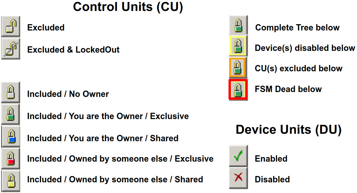
The ECS provides the Interface to the Operator. The Sub-systems have an hierarchical tree structure, where each Tree Unit behaves as a Finite State Machine (FSM). There are 4 domains:
HV: Equipment whose operation is related to the LHC State (Ex: High Voltages)
\(ERROR-> OFF -> STANDBY1 -> STANDBY2 -> READY\)
DCS: Equipment whose operation is related to a running period (Ex: LV)
\(ERROR-> OFF -> READY\)
DAI: And needed as Data Acquisition Infrastructure (ex: a crate)
\(ERROR-> OFF -> READY\)
DAQ: Equipment whose operation is related to a “RUN” (Ex: RO board, HLT task)
\(ERROR-> NOT\_READY -> CONFIGURING -> READY -> RUNNING\)
The Main tool of the ECS are:
RunControl: Handles the DAQ & Dataflow, Allows to: Configure the system, Start & Stop runs
AutoPilot: Knows how to start and keep a run going from any state.
BigBrother: Based on the LHC state, it Controls SD Voltages, RunControl (partially) VELO Closure (not yet)
Run Control
Launch main panel with:
/group/online/ecs/Shortcuts319/LHCb/ECS/RunControl.sh
Activity
“Activity” defines the configuration settings - “recipe” - which will be applied by all sub-systems on Configure. The Activity contains the global run settings
CONFIGURATION STEPS (before starting a Run)
Select the Sub-Systems & Sub-Detectors Included (normally ALL for Physics)
Choose/check the “Activity” (Will be communicated)
Check the “Trigger Config” (Will be communicated)
Check Data Destin./Type (“Automatic” for Physics)
Switch_ON AutoPilot 6. Look at “Messages”
Some Tips: Configuring & Starting a RUN
A When a new Activity is applied: Most Sub-systems and Sub-detectors get Reset. If needed also Deallocated (when different resources needed)
DCS & DAI Have to be READY in order to “Configure”: DCS & DAI Don’t accept commands from top-level, Go inside: Can send Switch_ON to individual Sub-Detectors (but please check with Sub-Detector piquet)
“Recover”, “Configure”, “Start” should always be sent from the top, but “Reset” can be sent directly to sub-detectors/sub-systems
Monitoring can take long to Configure: Be patient… and in extreme cases, could be “Ignored” then “Included” at run-time (but don’t forget to include as soon as possible)
While RUNNING:
Monitoringcan be manipulated while running (careful while closing VELO,Monitoringis needed)“Fast Run Change”: command
CHANGE_RUNcan fix DAQ problems (equivalent to \(Stop_Trigger-> Switch\_ON~Autopilot\))“Pause/Continue”: command
PAUSE_CONTINUE_RUN(can fix DAQ problems without changing Run Number)To Reset a Sub-Detector no need to
Stop_RUN: \(Stop\_Trigger -> Reset SD -> Switch\_ON Autopilot\)When changing operation mode or Cnfiguration always STOP_RUN first
When Excluding a SUb-detector for local work use
Exclude & Lockoutso that it gets rememberedAutopilot: in general leave it
ON, if goes onHELPswitch it toONorOFFbut not leave it inHELP
Troubleshooting & Recovery
Problems OR Recovery |
Actions |
|---|---|
No Input/Output Rate |
Try |
Most drastic DAQ recovery (but long ~5 minutes) |
|
When a
Sub-System
is in
|
look at the Message box, might give hints. Issue
“Recover” from the top first, Try a few times
|
EB+HLT1
repetively
in
|
Go down the tree to a node in ERROR and check which task has a problem: if is Allen: RTA piquet responsability, otherwise probably Online piquet |
Big Brother
Based on LHC state, proposes handshakes and simple confirmations. It
controls voltages and Run Control. activate it with
/group/online/ecs/Shortcuts319/LHCb/ECS/BigBrother.sh
The Voltage Control Table list the required HV state per Sub-Detector and for each LHC state.
There are 2 other Run Control Instances:
/group/online/ecs/Shortcuts319/LHCb/ECS/HLT2RunControl.sh
/group/online/ecs/Shortcuts319/LHCb/ECS/AlignRunControl.sh
Tips & Troubleshooting
Several mechanisms rely on the LHC State: Always make sure you confirm from the big box!
Handshake goes to “Problem” after 5 mins (warns after 3): Don’t panic, but react quickly
Slow prepare: Once the subsystem is ready PROBLEM switches to READY automatically
Sub-detector in error: As soon as error is solved or excluded (careful!!) PROBLEM switches to READY automatically
You might be contacted by LHC for explanation and time estimate
Alarm Screen
Launch it with
/group/online/ecs/Shortcuts319/LHCb/LBECSINFO/AlarmScreen.sh
at startup click on “Load filter…” on top right and select “ExcludeBadSystems”
normally this screen is empty: every alarm should be followed up by calling the appropriate piquet (and send it to the logbook with the button)